A circuit crossing is created when you add a pole to an existing tapoff pole.
To create a circuit crossing, follow these steps:
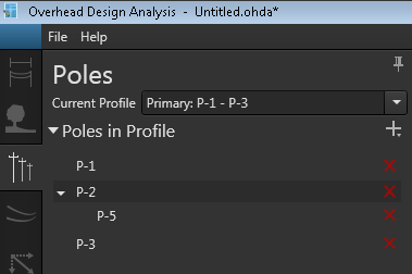
- Create a new tapoff pole or select the existing tapoff pole from Poles in Profile where you want to create the circuit crossing. In the following image, the existing tapoff pole is P-5. Notice that P-2 is highlighted in the image, which is the pole to which the tapoff pole is attached. Select P-5 to proceed.
- Optional. Add an assembly component to the selected tapoff pole. This addition adds the assembly to the tapoff pole and to the inline pole where it is attached.
- Click the plus (+) symbol next to Poles in Profile, and choose Complete Circuit Crossing.
- The Add Pole form displays in the left pane. By default, the attributes for the new pole match those of the pole you selected initially. Modify the values as necessary. While the Reference Pole field is available on the form, you cannot change the reference pole for a tapoff pole.
- Set the line angle for the incoming line. By default, the angle places the pole opposite to the existing tapoff pole.
- Click Create to place the new tapoff pole in the design. The circuit crossing is complete with the addition of this 2nd tapoff pole.
- Optional. Click Calculate to analyze the new pole.
 |
If you have assemblies and cables on the existing tapoff pole before you create a circuit crossing, OHDA extends the assembly and cables to the new tapoff pole; otherwise, you must complete the circuit crossing by adding assemblies and cables to the poles after the second tapoff pole is added to the design. |